Wade Engineered Self-Supporting Retaining Wall

An engineered precast concrete retaining wall system for civil, commercial, rural and residential projects. Available in four standard heights from 1.2 m to 2.4 m, with custom units, angles and finishes available for project-specific wall layouts.

Engineered & Self-Supporting
Available in multiple sizes
40 MPA CONCRETE
PS1 AVAILABLE

An engineered retaining system built for straightforward installation

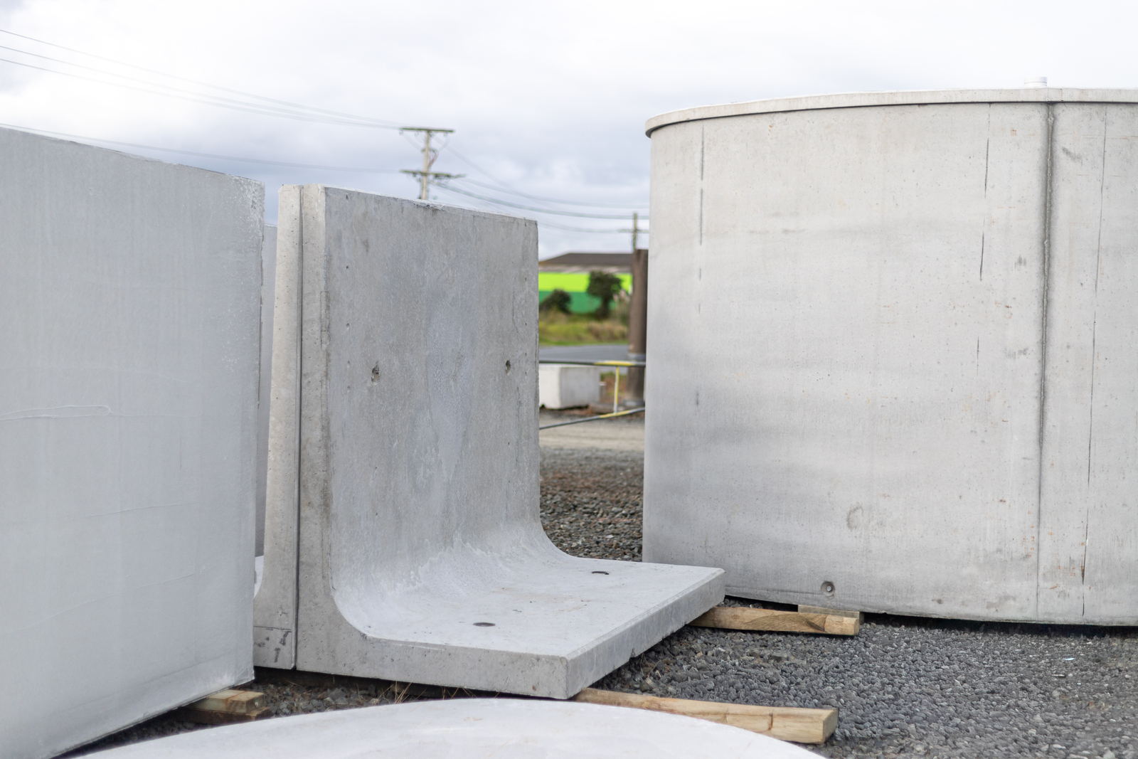
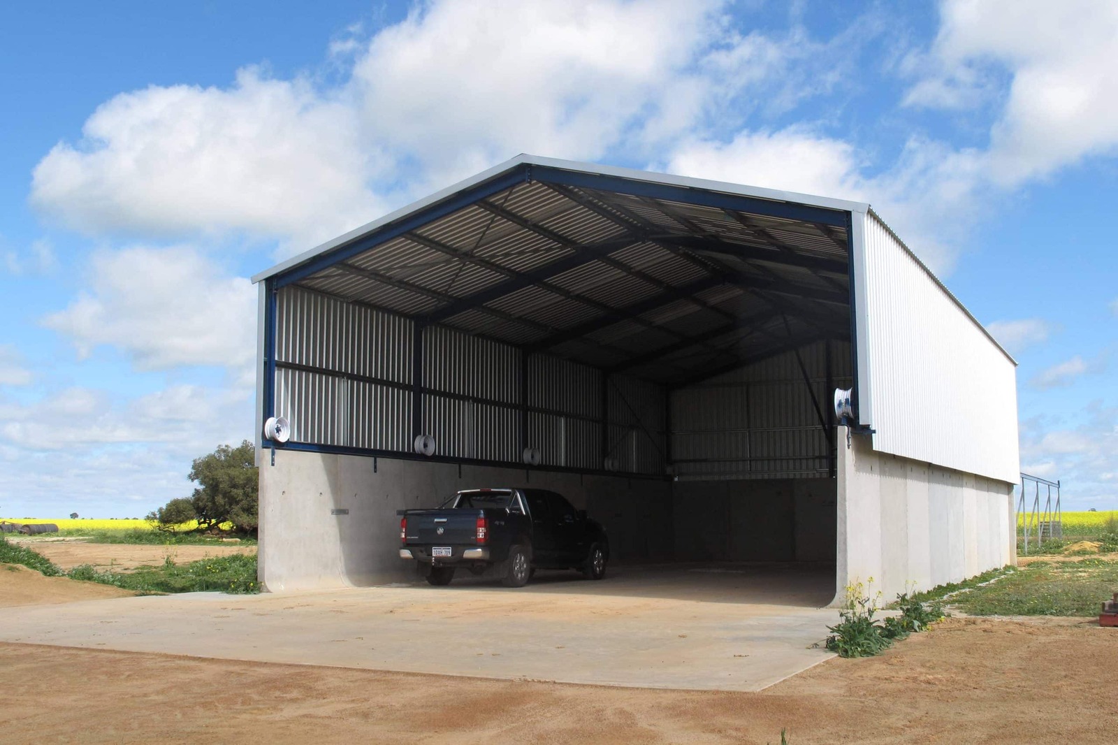
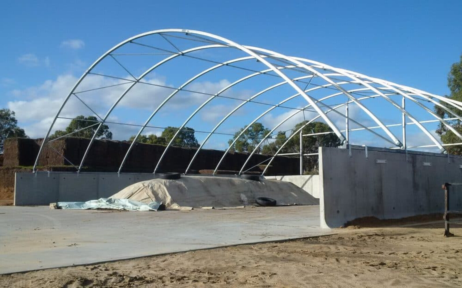
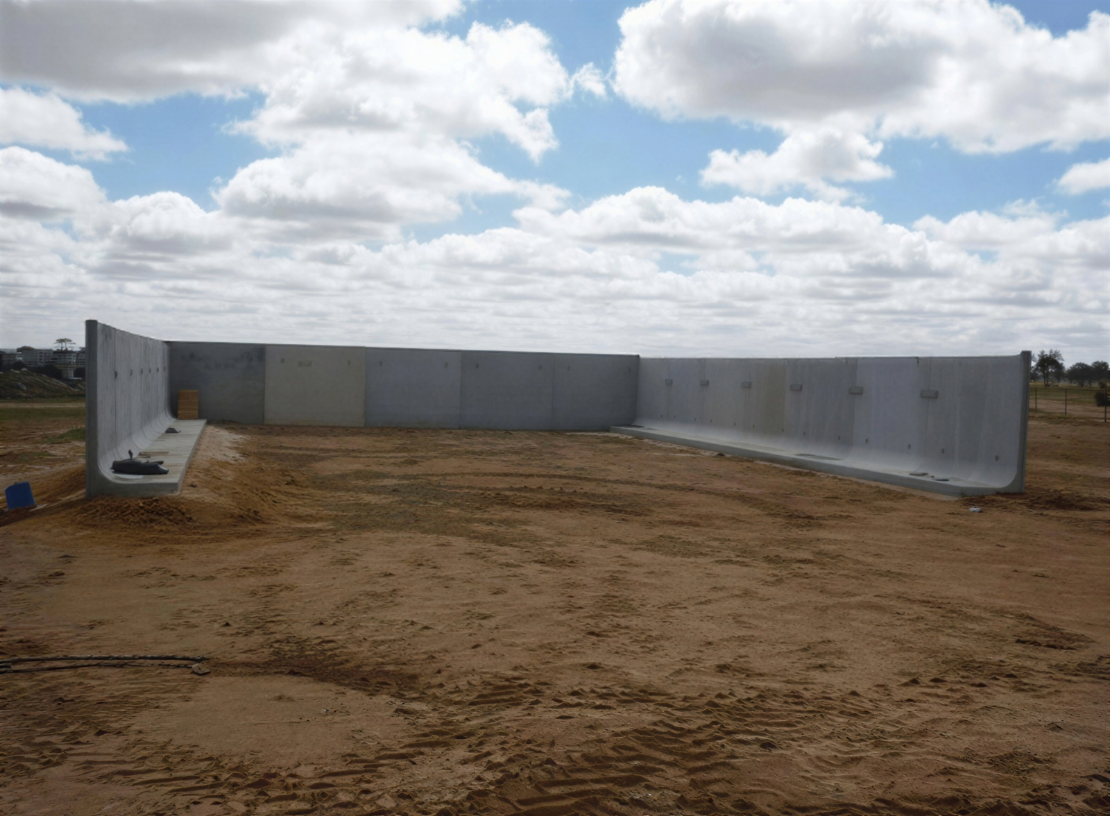
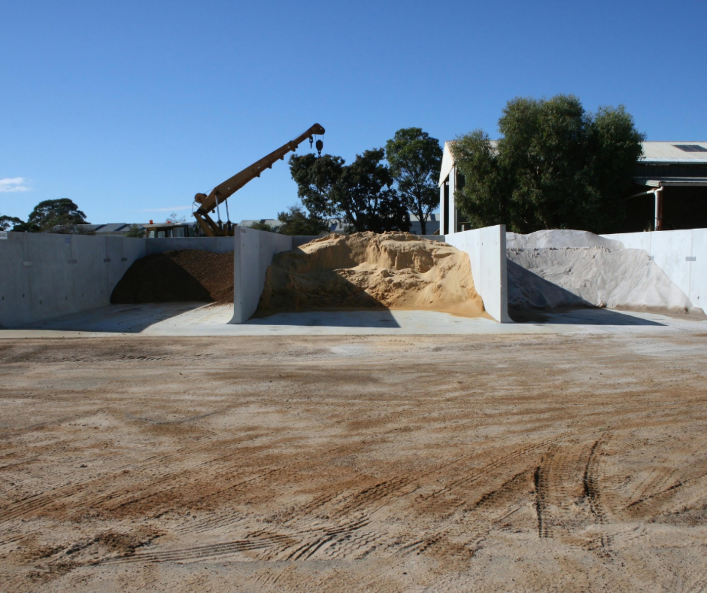
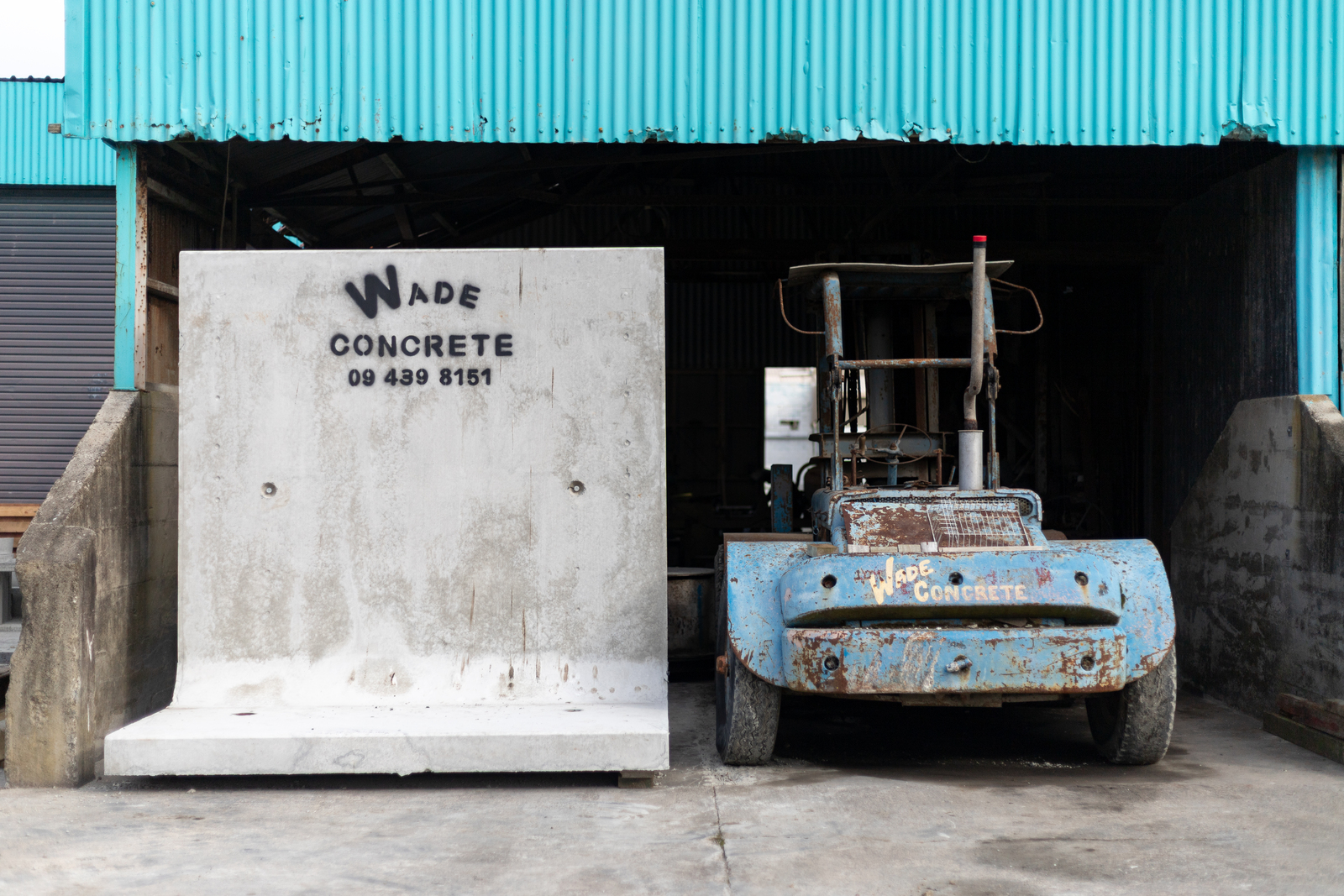
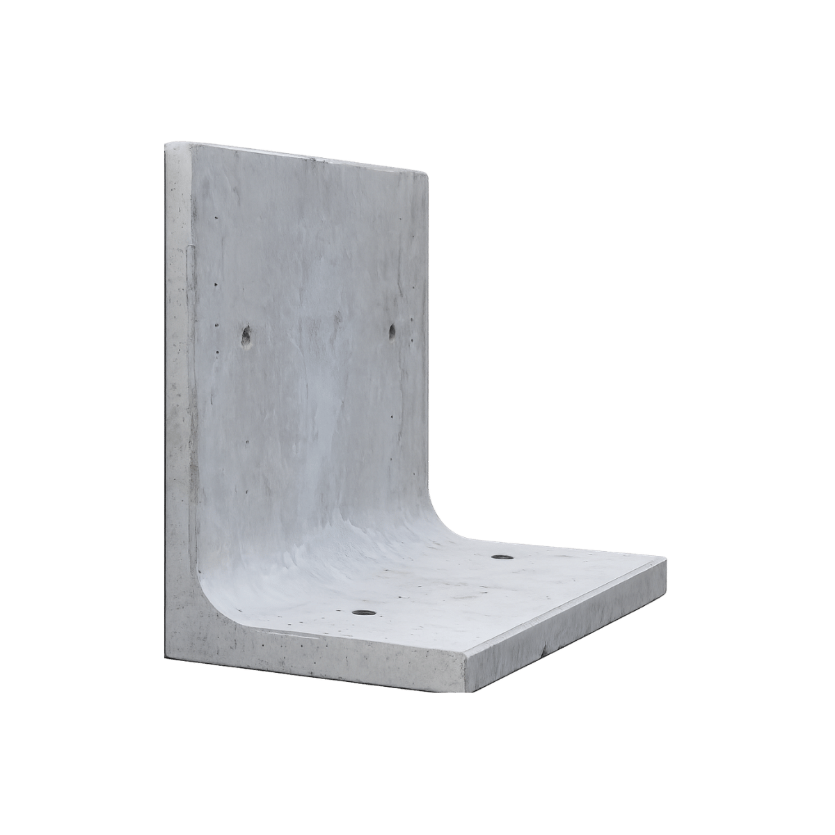
The Wade L-Block is an engineered precast concrete unit used to retain soil, manage changes in ground level and create usable space across civil, commercial, rural and residential projects.

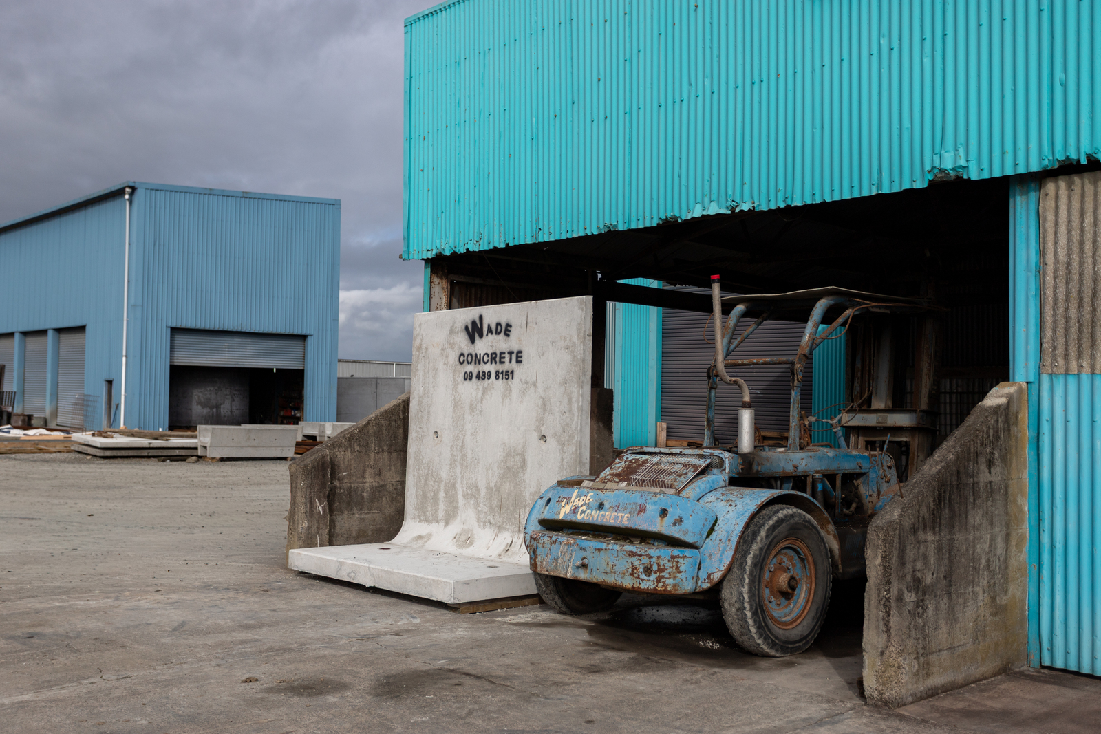
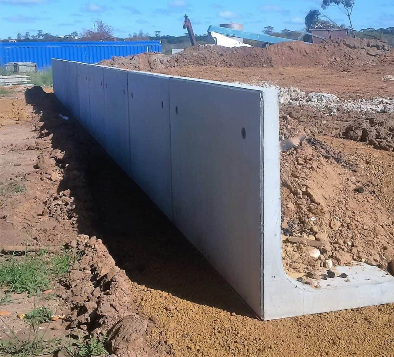
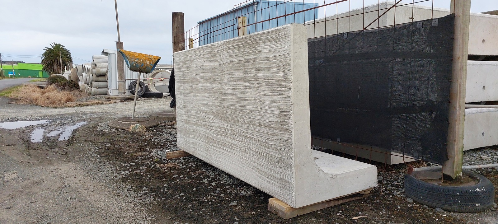
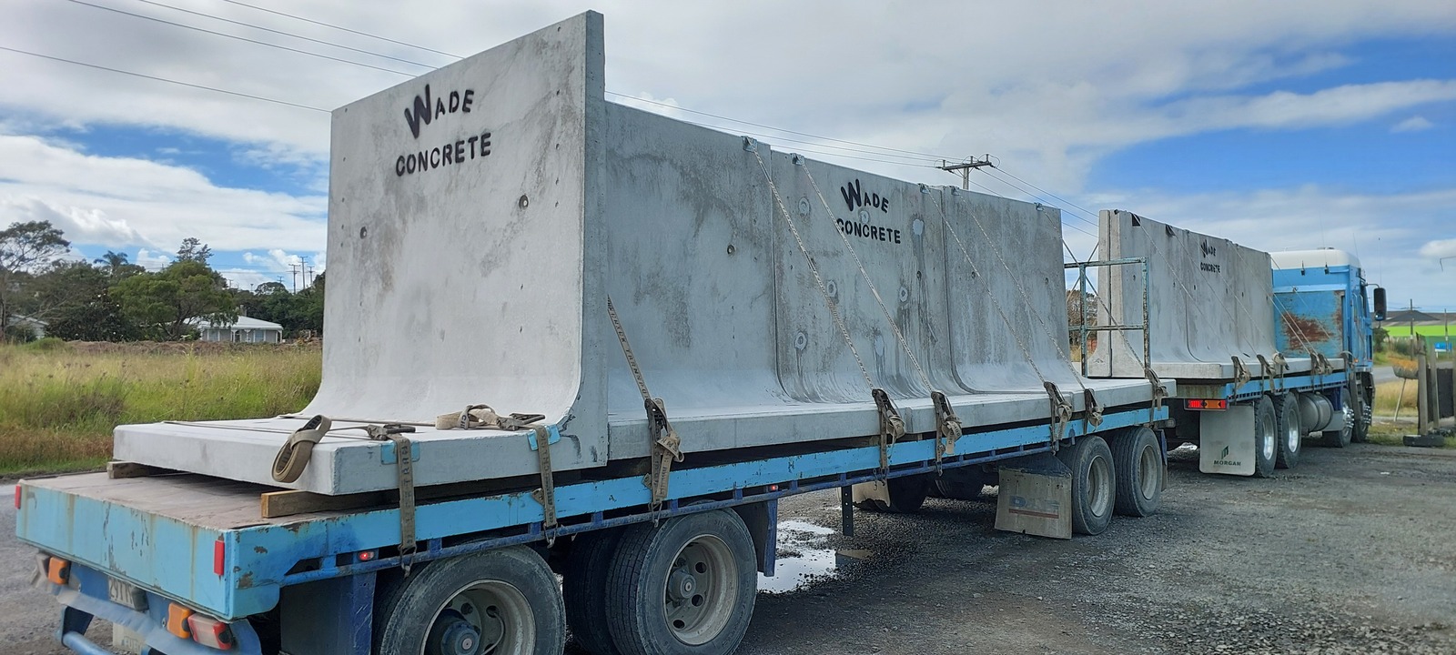
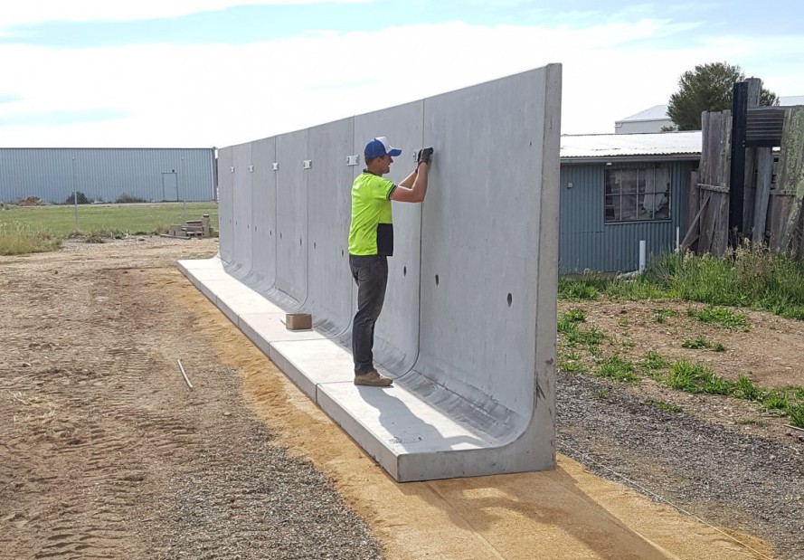
Its L-shaped design combines a vertical retaining face with a horizontal foot, creating a self-supporting wall system when installed on a correctly prepared foundation.

Each unit is manufactured from reinforced 40 MPa precast concrete and arrives on site at full strength. This reduces on-site formwork, concrete pouring and curing time, allowing the wall to be installed and backfilled in accordance with the project-specific engineering requirements.

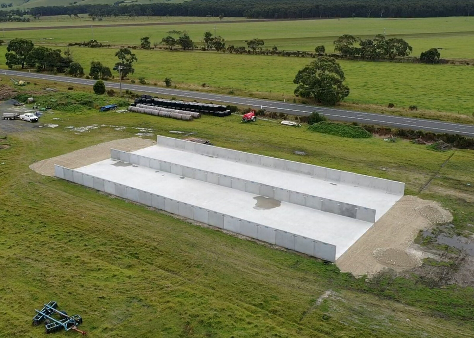
Standard units can be combined with corners, stepped sections, tapered blocks and custom units to accommodate different wall layouts.

Wade L-Block's Egineered Self-Supporting Retaining Wall (12)
CONFIGURATIONS & OPTIONS

Standard sizes and project options

Standard sizes

Wall height Unit length Foot depth Unit weight
1.2 m 2.4 m 0.8 m 1,710 kg
1.6 m 2.4 m 1.0 m 2,240 kg
2.0 m 2.4 m 1.2 m 2,610 kg
2.4 m 2.4 m 1.4 m 3,100 kg

Wall configuration options

The L-Block system can be configured using:

• Standard L-Blocks
• Stepped blocks
• Fixed 90-degree corners
• Corner joining units
• Tapered blocks
• Custom units

Connections

Optional 10 mm galvanised brackets are available for locking adjoining wall units together.

Bespoke options

L-Blocks can also be manufactured in custom heights and angles to suit specific project requirements.

Available finishes include smooth, broom-finished, rock-textured and timber-look surfaces. Other custom finishes are available on request.

Dimensions, reinforcement and unit weights may vary according to wall height and engineering design. Confirm product availability with Wade Concrete before finalising the project specification.

product photos

TECHNICAL DETAILS

Specifications

Additional information

Product type

Engineered self-supporting retaining wall

Construction

Reinforced precast concrete

Concrete strength

40 MPa

Standard unit length

2.4 m

Standard heights

1.2 m, 1.6 m, 2.0 m and 2.4 m

Lifting

Cast-in lifting points

Engineering documentation

PS1 design producer statement available on request

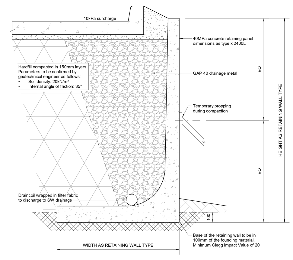
Wade L-Block Technical Drawing
IMPORTANT INFORMATION

Engineering and installation requirements

The wall, foundation, drainage and backfill requirements must be designed for the specific site. The design should account for the retained height, ground and soil conditions, groundwater, nearby structures, surcharge loads and access for delivery and lifting equipment.

Prepare, compact and level the foundation in accordance with the engineering design. The finished base must provide uniform support beneath every unit. The standard technical detail shows the wall base set into 100 mm of founding material with a minimum Clegg Impact Value of 20, but project-specific engineering requirements take precedence.

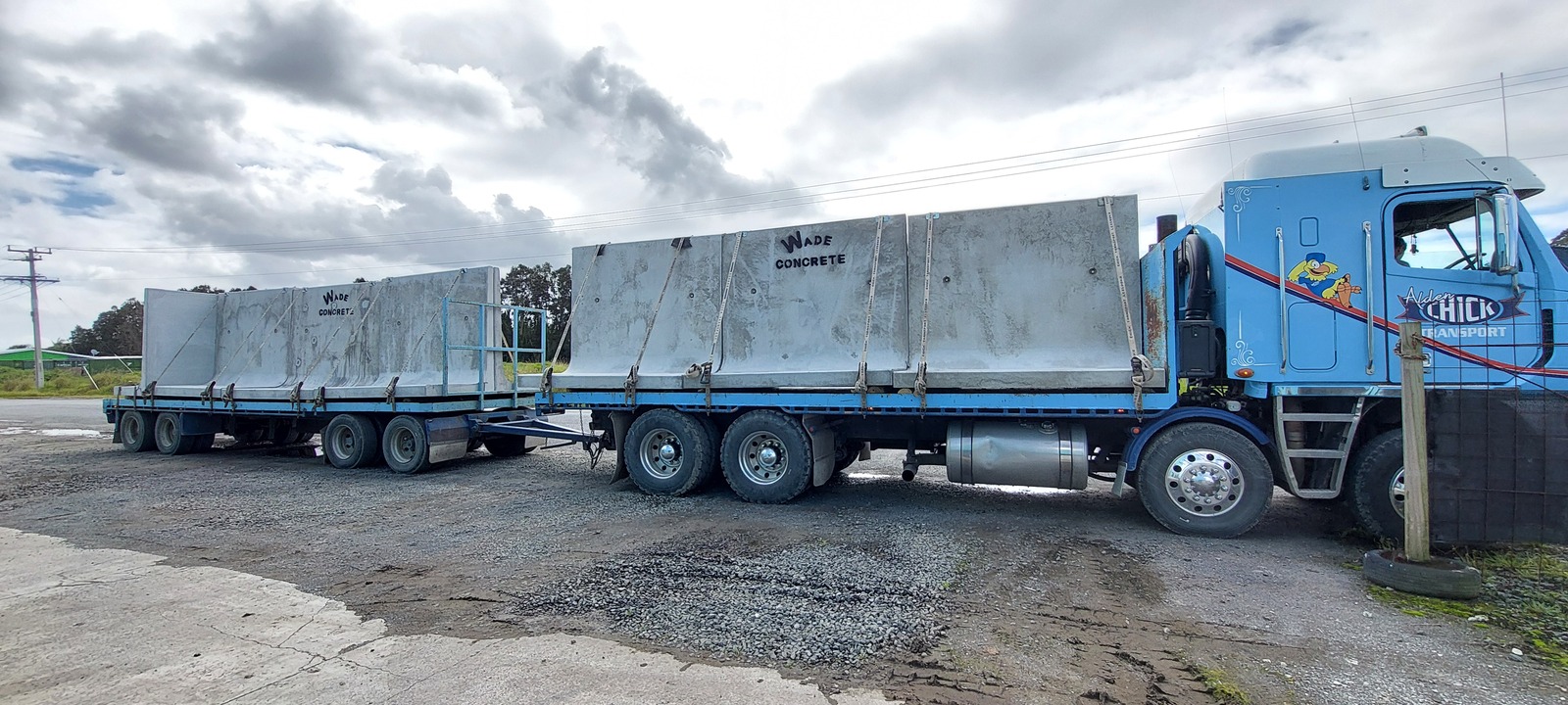
Lift units only with suitable certified lifting equipment connected to the designated cast-in lifting points. Position each block to the required alignment, level and spacing.

Connect adjoining units using the specified bolts, brackets and jointing system. Seal joints where required to prevent soil or drainage material from escaping through the wall.

Proper drainage is critical. Install the specified drain coil, drainage aggregate, filter fabric and suitable discharge points to prevent hydrostatic pressure building behind the wall.

Place and compact approved backfill in controlled layers in accordance with the engineering requirements. The standard detail specifies hardfill compacted in 150 mm layers, with the final requirements confirmed by the geotechnical engineer.

Installation must follow the project-specific engineering design and approved installation requirements. A PS1 design producer statement is available on request to support consenting and project documentation.

Need pricing or advice on this product?

Talk to our team about suitability, delivery and pricing for your site.